GU50 SingleEnd Amplifier
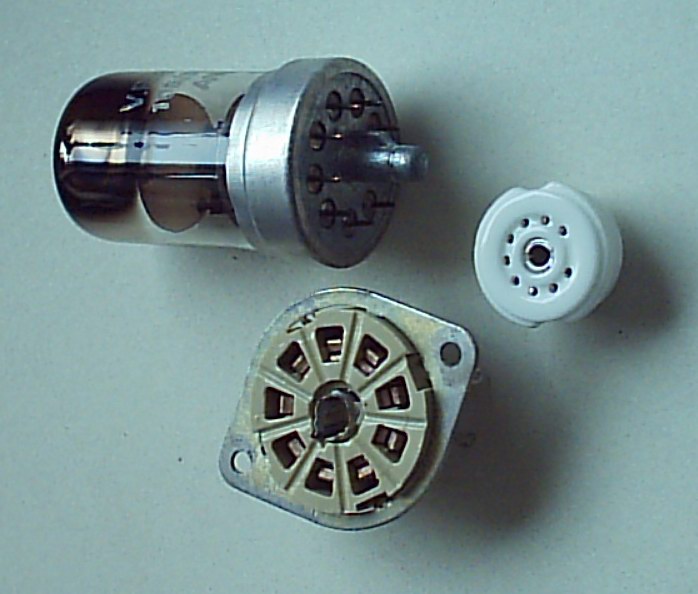
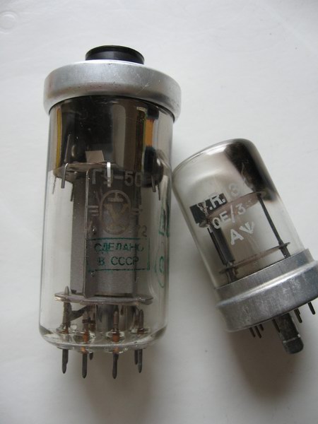
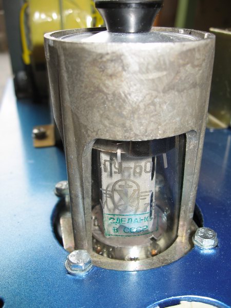
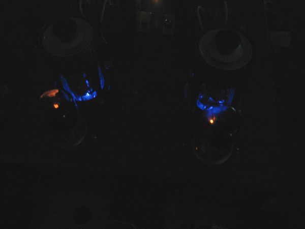
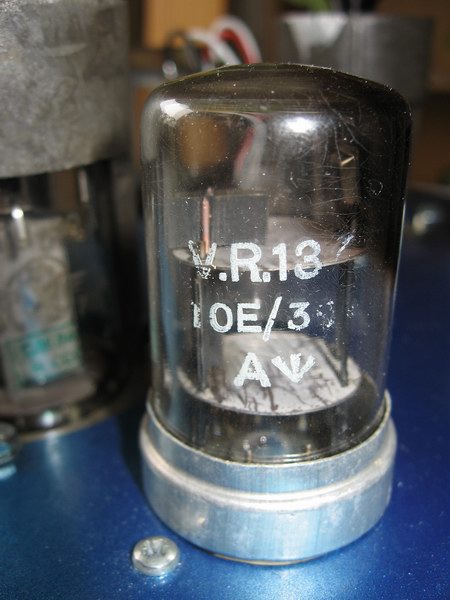
I scratched the GU50 as I believe I ruined the tubes - they could be positioned in almost any position if the "collar" was removed. My GU50s glowed bright orange!
After som rethinking I converted the amps to 6550SE - se separate page.
And after more rethinking, have put aside all thoughts (well, almost) of a GU50 SE-amp. Rebuild my Priboi using GU50s - yes, or maybe.
Shortly after our return from Russia to Sweden in 1997 I decided to try to make up a PSE amplifier using the GU50s I had brought with me. The data was similar to EL34, but the valves looked smarter, especially with the socket and its "collar".
Lars Ohlsson of ElektroAkustik & Music plotted a schematic for me, but I never got time or energy to start a project, instead I aimed my energy towards two different kind of preamplifier - the AML+ that I had gotten from Russian and the Elektor Electronics' SRPP-amplifier, published some 15 years ago (or maybe even 20).
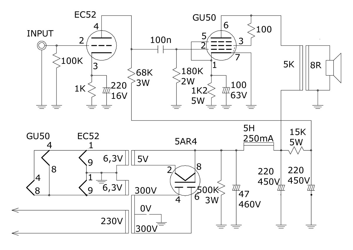
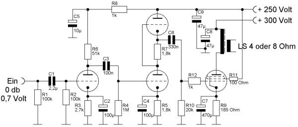
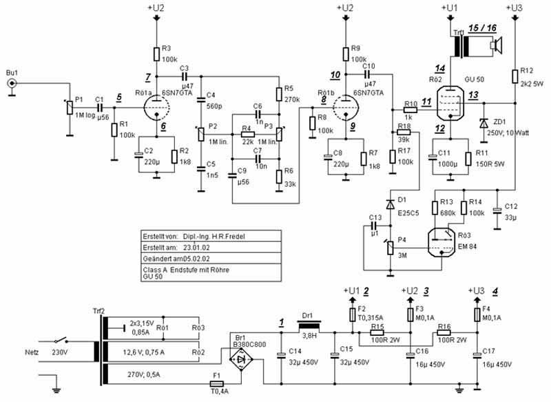
As i this spring came around to make up a simple pushpull amplifier using my EL84s and transformers I had obtained for nothing some 10 years ago i also started to make up plans for a singleend-amp. The search started and I was choosing between triodes and pentodes (beam-tetrodes). I had a pair of 807, but I was very interested in the 50CA10 triodes as I didn't want the mess with direct-heating or suicidal anode voltages. At this point I ended up at a German site with a lot of stuff around the GU50 and there were even two SE-designs, both looking rather nice.
Considering my ideas of a simple design schematic 1 was dropped. My knowledge in valve-design is a bit limited so I was really scared to try the second, but made a dramatic movement with Photoshop's erase tool and swiped the indicator tube away together with the tonecontrol.
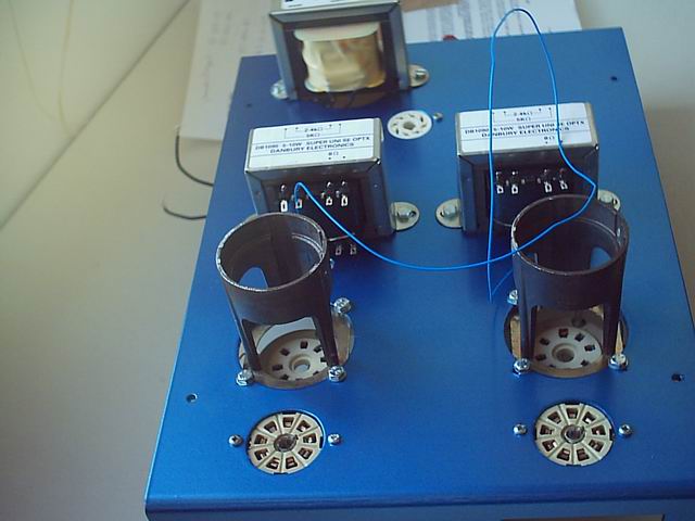
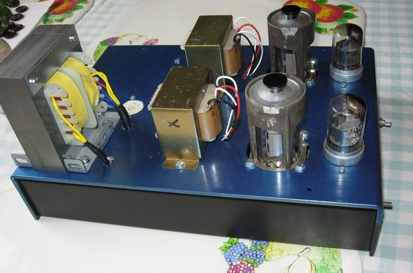
I had a few ideas of what the end result would look like. I started to check sources for transformers and even though I found some cheap suppliers noone of them answered my requests for prices. This was a bad stroke. Those companies were selling not only OP-transformers, but mainstransformers as well, and those were perfectly fitted for my project - correct voltages and currents. So back to square one I made an enquiry at a Swedish manufacturer of mainstransformers and at the same time decided to go for a monoblocked design. Two transformers were not dificult to make and I was left with the problem of finding the OP-transformers.In order to get somewhere I finally decided to order a pair of Hammond transformers from a guy in Sweden - the same, by the way that supplied the chassis (Hammond) and chokes (Hammond).
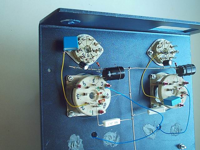
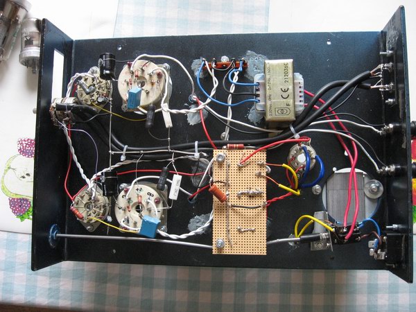
I am still waiting for the transformers, there's a list of components to be bought, but the project has advanced far. The chassis are drilled (and filed), painted and ready to be filled with electronics.
Finally got this answer from a member of a forum:
"Hi.
Thanks for the info, downloaded the schematics, its very basic in design and I can see a couple of flaws.
The first being that the first valve could see some feedback from the srpp driver which follows it, you are correct in increasing the power supply resistor as this would increase the impedance between the two stages.
As the second stage employs a valve that is effectively at a higher than ground potential, it is wise to float this as the valve, otherwise you could burn it out if the heater - cathode voltage is exceeded.
you could remove C2 to increase the local feedback and reduce the gain of this stage, this would make it more stable and stop the risk of oscillations on transients, this could also drop some of the inherent distortion of the circuit.
Also grid stopper resistors are a worthwhile modification, put a 1K resistor in series with the first (after R2) and second stage signal (after R4) grids, this also helps stability.
You could remove the input capacitor (C1) if the DC point on the first grid is below 5mV, this would improve sound performance.
Bypassing C5 and C9 with a small value ( 0.22uF) polyester would also improve power supply decoupling and therefor reduce any tendancy to oscillate.
If the above mods are carried out, you should have an unconditionally stable amplifer
Good luck
Chris"
SCHEMATICS
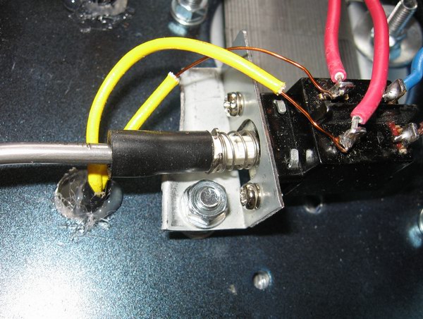
PHOTOS
LINKS
GU 50 - SE-Verstärker 2x50W ve dvojcinné B tr. s GU50 Verstärker mit GU 50 in Klasse A–Betrieb 35-Watt Mischpultverstärker mit LS 50 - Gegentaktendstufe Gegentakt-Verstärker in AB-Betrieb für GU 50 Röhren-Verstärker mit der LS 50 (GU 50) Planung und Bau eines Verstärkers mit der LS50 / GU50 Wzmacniacz mocy m.cz. UM-50